Wall Footings - Modeling
Here we will talk about the steps in modeling a wall footing and get into advanced wall footing modeling considerations. We will also talk about which type of wall footing would be appropriate for your application.
- For more information on defining wall parameters, see Wall Footing Definitions.
- For more information on calculation details, see Wall Footings - Design.
- For more information on the output, see Wall Footing Results.
Wall Footing Types
There are three types of wall footings you can model in RISAFoundation: retaining walls, strip footings and generated slab/stem wall combination. See the Draw Wall Footings section for how you select each option.
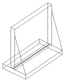
Retaining Wall
This is the traditional retaining wall. This type of wall will perform all stability checks (sliding, overturning and soil bearing) due to hydrostatic pressures and any superimposed load on the wall. This wall type is a single entity in that the wall and footing are considered together and defined in the Wall Footing Definitions Spreadsheet.
![]()
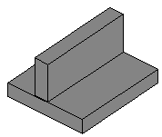
Strip Footing (Gravity)
This is a simplified version of the retaining wall and would be used in cases where you have a simple strip footing layout. Hydrostatic pressures on the wall are not a concern here. This type of wall footing pares down the input and output in the program, removing a lot of the complexity necessary for retaining walls, but not required for a simple strip footing. This wall type would generally be used for simple gravity loads. This wall type is also a single entity in that the wall and footing are considered together and defined in the Wall Footing Definitions Spreadsheet.
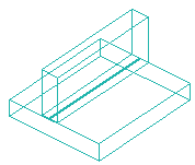
Strip Footing (Lateral/Custom)
This is a wall type that is really a generation utility that will create a slab, slab design strip(s) and a stem wall to represent your wall footing. This type of footing would not be controlled by the Wall Footing Definitions, but rather by each individual entity (slab, slab design strip and stem wall) separately. This option generates these elements one time and then allows you to edit/modify these elements as necessary.
The main purpose of this type of wall is to allow for any customization and to allow the program to perform a finite element analysis (FEA) of the footing. The other two wall types do not perform an FEA on the footing itself.
![]()
Draw Wall Footings
You can create new wall footings using a Drawing Grid, Project Grid or drawing point-to-point clicking existing points. You can set all of the wall footing properties up front, or you can modify these properties after you draw the wall footing. Graphically modifying properties is discussed in the next section.

Click on image to enlarge it
To draw wall footings:
- If there is not a model view already open, go to the View ribbon.
- Click the Open 3D Views icon in the Window section to open a new view.
- If you are not drawing between existing points, you need to create a drawing grid or define nodes in the Node Coordinates Spreadsheet.
- Go to the Home ribbon.
- Click the Wall Footing icon in the Draw Elements section.
- Choose the wall footing type, including the Definition, if applicable.
If you are modeling a Strip Footing (Lateral), you have the option to make the wall footing continuous by checking Keep Wall Continuous in the Strip Footing Generator dialog (shown below). Here, you can input the properties of your composite slab, slab design strip and stem wall entity. This dialog is similar to the Wall Footing Definition Editor.

Click on image to enlarge it
-
In the Properties panel, set the wall footing properties.
-
To start drawing wall footings, click on points or grid intersections with the left mouse button. The coordinates of the closest point or grid intersection to your cursor are displayed on the screen near your cursor.
The first click defines the Start Point of the first wall footing. The second click, and each click thereafter, defines the End Point of the first wall footing and also the Start Point of the next wall footing so that you can continue to draw. To stop drawing, click the right mouse button. You can then start drawing somewhere else with the left button.
The new wall footings are shown on screen and recorded in the Wall Footings Spreadsheet.
- To stop drawing altogether, click the right mouse button again or press the Esc key.

- If you have not created Wall Footing Definitions ahead of time, you can create a new definition by clicking any of the
 (ellipsis) buttons in the Properties panel. This will open up the Wall Footing Definition Editor dialog.
 - You may undo any
mistakes by clicking the
 Undo icon in the Quick Access toolbar.
Modify Wall Footings
The instructions below detail how you modify Retaining Walls and Strip Footings (Gravity). Modifying Strip Footings (Lateral/Custom) requires you to edit the individual entities (slab, slab design strip(s) and stem wall) that make up that wall footing.
For non-custom wall footings, you may view and edit the wall footing data in the Wall Footings Spreadsheet. You may also click a single wall footing or select multiple footings to view and edit the properties in the member Properties panel. You can use the tools in the Modify tab to graphically modify the wall footings in the 3D View.

Click on image to enlarge it
To modify wall footing properties:
- If there is not a model view already open, go to the View ribbon.
- Click the Open 3D Views icon to open a new view.
- Click a single wall footing, or select multiple wall footings that you wish to modify.
- If you have multiple elements selected, specify which element type to view properties for using the Selection Properties drop-down in the Properties panel.
-
Set the parameters for the wall footings within the Properties panel.
Wall Footings Spreadsheet
The Wall Footings Spreadsheet records the properties for the wall footing elements and may be accessed by selecting Wall Footings from the Data Entry drop-down on the Spreadsheets tab of the ribbon, or by clicking Wall Footings from the Data Entry section of the Explorer panel.

Click on image to enlarge it
Label
This gives a unique label to each wall footing in the model.
Start Point/End Node
This defines the start and end location nodes for the wall footing. The nodes can be modified directly in the spreadsheet.
Definition
This is the Wall Footing Definition to be used. This definition gives all of the other information required for design of the wall footing.
Wall Footing Modeling Tips
Here are some tips to think about when modeling wall footings.
Wall Footing Orientation
When drawing wall footings, click on two points to define the length of the wall footing. The wall (with footing) will be drawn so that the centerline of the wall lines up along the two nodes defining the wall. These elements, though drawn in a 3D rendering, are really just line elements.
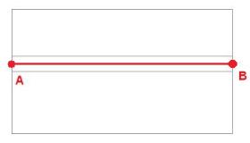
Figure 1: Plan View of Wall Footing
When drawing a wall footing, the orientation of the local axes for the wall will always have the local x-direction parallel to the line that defines the two nodes drawn.
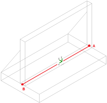
Figure 2: Isometric View of Wall Footing
Here, we can also see the orientation of the positive z-axis and that the soil is on the positive z-axis side of the wall footing. Keep this in mind when drawing your walls.
For example, if you are drawing basement walls for a structure, make sure to draw in a counter-clockwise fashion. This will ensure that the soil is on the exterior side of the walls. Note that this is only applicable for Retaining Walls.
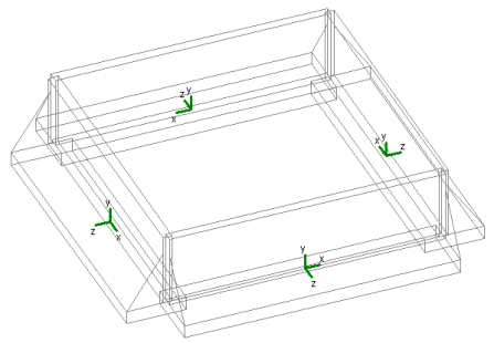
Figure 3: Basement Walls Drawn Counter-Clockwise
Load Categories
Once you have defined all of the required properties in the Wall Footing Definitions Spreadsheet, the program calculates the weights, hydrostatic loads, soil pressures, etc, and applies them to the wall for analysis and design purposes. The program also places these loads in load categories for you automatically.
-
Dead Loads (DL): Weight of concrete and weight of soil.
-
Live Loads (LL): Surcharge loads (applicable only to retaining walls).
-
Hydrostatic Loads (HL): Any lateral pressure/hydrostatic loads (applicable only to retaining walls).
- Any loads applied to the top of the wall footing will be considered under the load category they are applied with.
- If you have a sloped backfill on your retaining wall, a portion of the hydrostatic loads will be applied in the vertical direction of your wall. The cosine of these forces will be applied horizontally as a pressure. The sine of these forces will be applied as a vertical force that is conservatively lumped at the top of the wall.
- Water pressure (if there is a water table present) will always be assumed to act horizontally, even in the presence of a sloping backfill.
- It is possible for the horizontal component of hydrostatic force to act ABOVE the height of the wall. All loading that occurs above this height will be lumped as a point load right at the top of the wall.
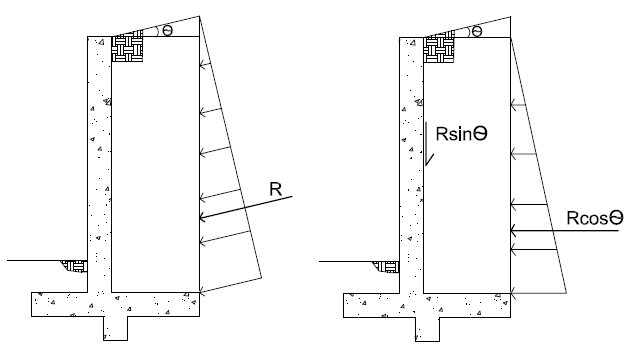
Figure 4: Hydrostatic Loads with Sloped Backfill
Loading of Wall Footings with Externally Applied Loads
Wall footings will accept externally applied loads to them, but only loads applied to the top of the wall. To apply loads to a wall footing, you must apply the loads to the centerline at the base of the wall.
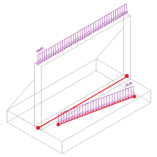
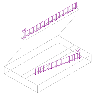
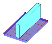
Figures 5A & 5B: Wall Footing with External Loads
In the figures shown above, we can see (from the red lines) how the loads were applied and how they ended up on the wall footing. The distributed load applied along the centerline of the wall ended up being applied to the top of the wall and will be analyzed/designed as such. The other load did not line up with the centerline of the wall, so it will not be considered at all in the wall footing design.
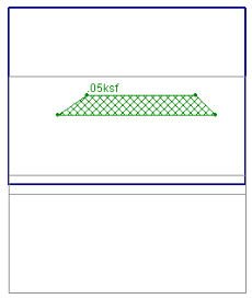
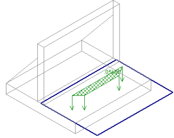
Partial length distributed loads (even trapezoidal) and point loads work in the same fashion.
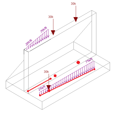
Figure 6: Wall Footings with Trapezoidal Dist. Loads and Point Loads
Looking at the model in a Plan View while drawing can make modeling these loads much easier.
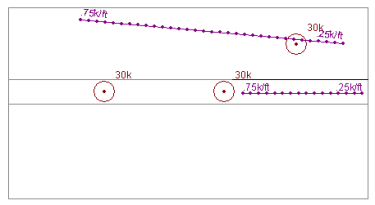
Figure 7: Wall Footing Loading shown in a Plan View
If you have two adjacent wall footings (defined by the same node), applying a point load at the common node will always place that load on the wall footing that comes first in the Wall Footings Spreadsheet.
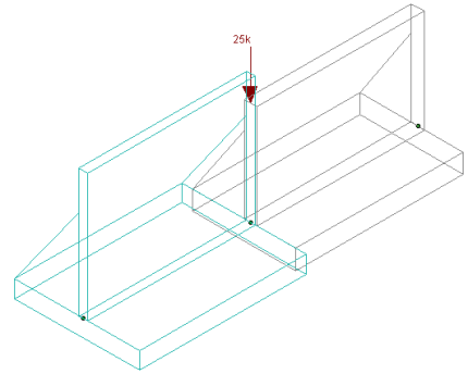
Figure 8: Two Adjacent Wall Footings with a Point Load
Connectivity with Other Elements in the Model
Non-custom Wall Footings in RISAFoundation have no connectivity to any other elements in the model, not even adjacent retaining walls. So while it is possible to connect beams and place slabs adjacent to the wall footing, no forces will be transferred between the two. Here are some examples where wall footings and other elements may seem to come into contact with each other.
- Beams and Wall Footings: Here it appears that the wall footing and a beam are in the same space. However, if any load was applied along the line where the beam and the wall footing overlap, the load would only be taken by the beam and none of the load would be seen by the wall footing.
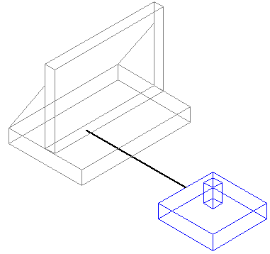
Figure 9: A Beam Overlapping with a Wall Footing
- Beams and Slabs: Slabs can be drawn so that they are adjacent with wall footings. Any load that is defined on the area of overlap of a slab and a wall footing will only be taken by the slab. The wall (and footing) will have no interaction with the slab.
Figures 10A & 10B: A Slab Overlapping with a Wall Footing
- Other Items that Overlap: Many other overlapping situations in the program are not handled and an error will be given at solution.
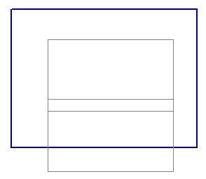
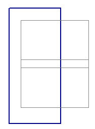
Figure 11: A Slab Drawn Overlapping the Wall Portion
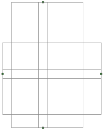
Figure 12: Two Wall Footings Where the Walls Cross
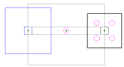
Figure 13: A Pile, Pile Cap, or Footing, that Intersects the Wall Footing Centerline